CLS700 Overview
Here’s our CLS700 Overview, we use two of these printers for our Core Elite systems because they produce extreme volumes of number plates, with minimal interaction. This page highlights the important parts and locations on the Citizen printer. Refer to this page when troubleshooting or to find out what a part is called or where it’s located.
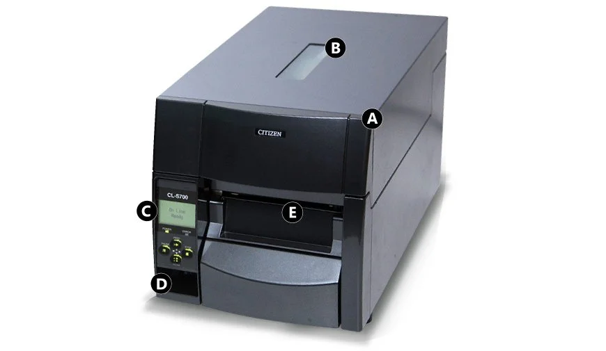
Front View
The front view shows the printers main controls, output and top cover. This is where most interaction with the machine occurs.
- A: Top Cover – Opens vertically to access the inside
- B: Top Window – View ribbon & media status
- C: Control Panel – Machine settings and alerts
- D: Power Switch – Toggles mains power
- E: Output – Printed media emerges here
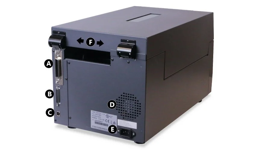
Rear View
The rear view shows the printers mains switch and power point, along with the 3 interface ports.
- A: Parallel Interface – Connect to PC via parallel cable
- B: Serial Interface – Connect to PC via serial cable
- C: USB Interface – Connect to PC via a USB cable
- D: Rear Vent – Discharges heat
- E: Power Socket – Power cord inlet
- F: Top Cover Hinges – Fixed hinge attachments
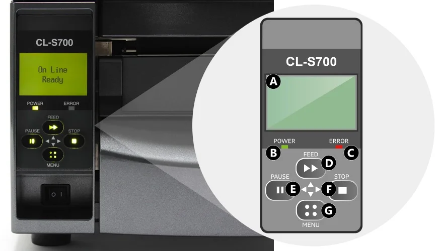
Control Panel
The control panel is where the user interacts with the printer, with options to begin, pause and stop operation.
- A: LCD Display – Shows printer status and settings
- B: Power LED – Lights up Green when on
- C: Error LED – Lights or flashes Red to indicate an issue
- D: Feed Key – Moves media into start position
- E: Pause Key – Pauses current print job
- F: Stop Key – Stops printing or cancels the alarm
- G: Menu Key – Enters printer configuration menu
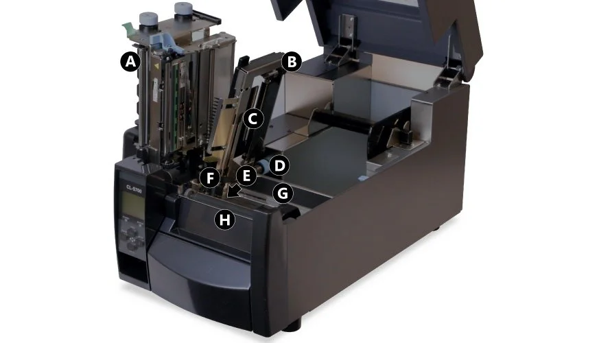
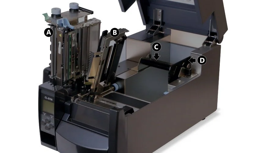
Inside
Inside the top cover you’ll find the print unit and media set-up controls. And of course the roll feed and media tray.
- A: Print Unit – Ribbon & printing unit
- B: Sensor Arm – Holds rear media sensor
- C: Rear Sensor – Detects media position – Adjustable
- D: Sensor Knob – Adjusts the left to right position of rear sensor
- E: Front Sensor – Detects media position – Fixed
- F: Left Media Guide – Fixed media guide
- G: Right Media Guide – Adjustable media guide
- H: Platen – Feeds and retracts media
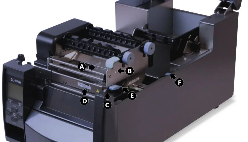
Media Alignment Controls
These controls help you to position, align and pull the media through the printing unit.
- A: Media Thickness Screw – Adjusts print unit offset to match media size
- B: Media Thickness Indicator – Window & markings for fine tuning
- C: Media Width Knob – Adjusts print unit pressure to match media width
- D: Media Width Indicator – Window & markings to fine tune print area
- E: Print Unit Lever – Opens or locks print head unit
- F: Sensor Arm Lever – Releases or locks the sensor arm
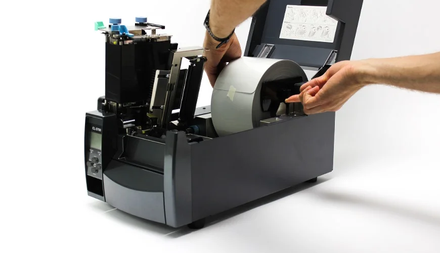
Roll Feed
- A: Print Unit – Lifts up for access to the roll recess
- B: Sensor Arm – Detects perforation notches or marks
- C: Media Arm – Holds reflective rolls
- D: Media Bar – Holds arm & helps feed media
Need Help?
This is a basic overview of the Citizen CLS700 Number Plate Printer. Please refer to your user or manufacturers guide for more up-to-date information. If you’ve an account, you can order replacement CLS700 Consumables from our online NP-Shop.
Our knowledge base contains articles with details on replacing this printers ribbon and loading media rolls. Not to mention its required operating conditions and approved printer settings. And has solutions to common number plate print issues and printer errors.

